|
telescopeѲptics.net
▪
▪
▪
▪
▪▪▪▪
▪
▪
▪
▪
▪
▪
▪
▪
▪ CONTENTS
◄
13.9. Eye spectral response
▐
14.2. ATM telescopes
► 14. TELESCOPES
PAGE HIGHLIGHTS
This last chapter is about real telescopes, as much as available
information allows,and raytracing can show. They are divided in
four groups: (1) early telescopes, from the time of Galileo up
to the 19th century, (2) ATM telescopes, interesting designs built
by amateurs, (3) commercial telescopes, those with a complete
(rare), or partial specs, but sufficient to come up
with a design substantially close to the real unit's, and
(4) professional telescopes, those used on observatories and
have their specs pulished.
How would the earliest
telescopes do in raytracing? Sure, we don't know the exact specs, but
what we do know allows a reconstruction of their overall level of
optical performance. How good was Galileo's big little refractor? Or
Isaac Newton's reflector, Hevelius' 150-foot long singlet monster,
Hershel's 40-foot big gun? Let's start from the beginning. Or, for that
matter, "Elizabethan telescope"?
GALILEO'S REFRACTOR
According to the Museo Galileo, in possession of the original Galileo's
telescope from ~1610 (Padua, Italy), it consists of a biconvex lens objective, 51mm
in diameter and 2.5mm thick, with 1330mm focal length, and a plano-concave
eyepiece lens, 26mm in diameter, 3mm thick, with -94mm focal length
(concave side toward eye). The objective lens has unequal radii, but no
specifics on which side is stronger (it makes little difference, since
spherical aberrations of this small f/26 lens remains very low).
The numbers imply ~14x
magnification, and the field of view is said to be about 15 arc minutes
in diameter. It gathers about 50 times more light than the average eye.
With this little instrument looking more like a long stick than a
telescope - and a few others similar to it - Galileo revolutionized our
view of the outer space: he found that the Milky Way is made of stars,
that the Moon is a planet-like body, four heavenly bodies revolving
around Jupiter, sunspots, phases of Venus, intriguing three-bodied
aspect of Saturn...
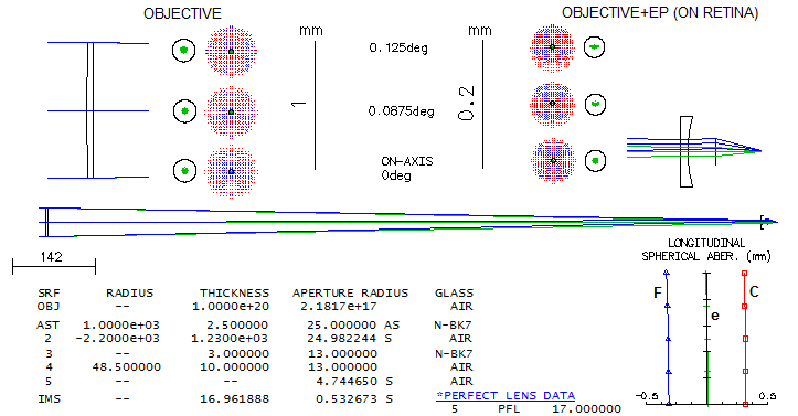
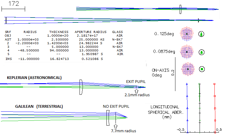
Here's how it raytraces:
The only significant aberration of the objective is longitudinal
chromatism, specifically, primary spectrum. With 3.2 waves P-V wavefront
error of defocus in the blue F line (486nm), and 2.8 waves in the red C
line (656nm), it is nearly twice as bad as an achromat having this much
of an error in these two lines, or roughly 100mm f/2.5 at best (because
secondary spectrum changes nearly quadratically, and the primary closer to
linear, as illustrated on FIG. 68).
However, due to much smaller aperture, it was less noticeable.
There is no mention of the objective being stopped down, as it is with
another, smaller Galileo's scope in the possession of the museum (37mm
objective diameter this time plano-convex - stopped down to 15mm, 930mm
focal length, original eyepiece lost). But another source ("The
world's oldest surviving telescopes", Bolt and Korey) states that
the objective "stops down to 26mm". In fact, most telescopes from this
era that still exist have their objectives significantly stopped down.
Self-evident reason is the commonly poor polish on the outer lens area,
but at least in some cases it could be to reduce chromatism as well. If
stopped down to 26mm, this objective would have its chromatism cut in
half, bringing it to the level of a 100mm f/5 achromat, or nearly so.
The "perfect lens" used to focus light exiting the eyepiece has focal
length of 17mm, the approximate effective f.l. of the eye. It doesn't
have significance other than it means that the Airy disc and the blurs
size are equal to those actually forming on the retina. The lens radius
of 4.7mm needed to fully absorb diverging light pencils for the 0.125°
field radius at 10mm lens-to-eye distance means that even this narrow
field was significantly vignetted toward the edge.
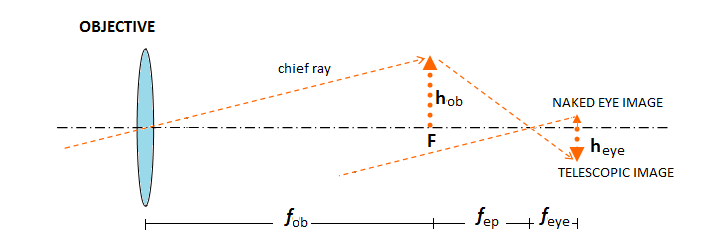
Note that the scale
indicates the physical image over five times larger in the focal plane
of objective, than on the retina. How is it that the final image appears
14x larger? The answer is that the image on the retina would have been
14x smaller without the telescope. Since eye effectively observes image
by the objective from distance equaling the eyepiece focal length, it
can be illustrated schematically omitting the eyepiece (shown is the standard,
Keplerian scheme, but the same principle applies to the Galilean). From similar
triangles, retinal
(telescopic) vs. objective's image physical size equals the proportion eyepiece's vs. eye's focal length. It is
smaller, physically, than image in the focal plane of the objective when
the eye's focal length is smaller than that of the eyepiece, but it is
larger than the naked-eye image, by a factor f
KEPLERIAN (ASTRONOMICAL) REFRACTOR
As the euphoria about the great new invention - Galilean
refractor - started to grow, the seed of what will bring an end to it
was already there. In his Dioptrice, published in 1611, Johannes
Kepler mentions different instrument, using two convex lenses to form an
inverted image, as a possible alternative to the just discovered
Galilean refractor. However, the fact that it remained a mention, while
he in the same publication gave a full analysis and optical explanation
to the Galilean refractor, indicates that Kepler at that point in time
wasn't aware of the crucial advantages of that alternative system. In
fact, he never came up with such analysis. It took several decades
before Manzini (L'occhiale all'occhio, 1660) and d'Orleans (Dioptrique
oculaire,
1671) accomplished that; the former qualitatively,
and the latter giving to it a complete optical analysis.
Due to such obscurity, what will become the "astronomical
refractor" had very sporadic use for decades after the Dutch invention.
On the other hand, potential for discovery of the Galilean refractor was
exhausted already in 1611, with the only new discovery after that being
Andromeda galaxy by Simon Marius in 1612. Main reason for it was the
limit to field size in the Galilean (or terrestrial) refractor,
ultimately setting the limit to magnification as well. In addition,
being a system without exit pupil, Galilean refractor had no possibility
for baffling the eyepiece, nor for optimal placement of observer's eye.
As such, it was ultimately replaced by the "astronomical telescope" -
the Keplerian refractor.
Here is raytracing example of it. To make the two
directly comparable, will use objective and eyepiece of the same focal
length as in the Galilean refractor above.
There is no appreciable difference between the two in the
axial correction or chromatism. However, the geometry of imaging through
the eyepiece clearly favors the Keplerian (for clarity, field angle for
this illustration is doubled to 0.25 degrees). Not only that it
converges all light pencils into an exit pupil, allowing the light of
all field point to use the optimal, central portions of the cornea and
eye lens, it also forms eye relief, for more comfortable eye placement.
On the other hand, divergence of the field pencils caused by the
negative eyepiece in the Galilean not only much larger eye pupil to pass
them through without vignetting, the very divergence, by sending
collimated pencils toward outer portions of eye's refractive surfaces at
an angle, results in inferior imaging of these pencils by the eye. The
former sets limit toward low magnifications, and the latter toward high
magnifications, since the divergence increases inversely to the eyepiece
focal length.
So, for two different reasons, eye has to be kept as
close to the lens as possible, making observing uncomfortable even in
the reduced range of magnifications. And eye strain directly diminishes
its imaging quality.
The only disadvantage of the Keplerian was its inverted
image, relatively unimportant for astronomical observing. It was simply
more capable as an instrument, and the rest is history.
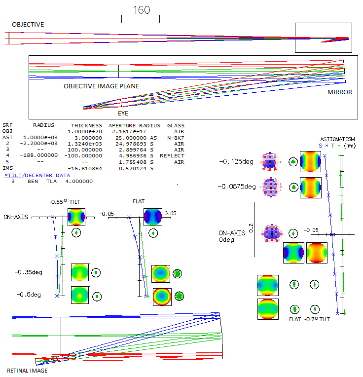
ELIZABETHAN TELESCOPE
During the 1990's, a few British authors (Ronan, Rienitz, Whitaker)
tried to document the claim that telescope was invented in the 16th
century Elizabethan England, decades before the Dutch invention
in 1609. They based their case mainly on the writings of two 16th
century English mathematicians, Thomas Digges and William Bourne. The
two, however, never came up with a detailed description, drawing - let
alone a prescription. They did have an idea of a telescope - or,
generally, magnifying instrument - but lacked the knowledge to have it
materialized. Bourne even sent a letter to Lord Burghley asking for
patent of monopoly and patronage for his project, which was most likely
left unanswered. The
idea was to use a convex lens objective and a concave mirror placed
after its focus, so that the light reflected from it forms parallel
pencils of light. The mirror would be tilted at a small angle, to allow
observer to keep his head out of incoming light. But Bourne, who wrote
about his idea much more extensively than Digges, had a faulty concept
of magnification, thinking it is determined by lens' size, rather than
focal length. That caused him to state that the objective has to be at
least a foot in diameter. Singlet of that size would be pretty much
useless in any practical length, due to chromatism, but appears that
Bourne wasn't aware of it.
Anyway, the concept of
using mirror for an eyepiece is valid, and interesting as well (so much
so, that there is a "reconstruction" of the Elizabethan telescope in the
Louwman Collection of Historic Telescopes in Hague; it is just a
model, since with its 95 mm f/5 singlet objective and large mirror tilt
wouldn't be able to produce usable image).
Here's how such telescope
would raytrace. To make it comparable to the Galileo's and Keplerian
telescope, will use identical objective and eyepiece (mirror) focal lengths (4th
surface is "perfect lens" of 17mm focal length acting as a perfect eye).
Surface 3 is dummy surface coinciding with the objective's focal plane, and showing
image height in it. Chromatism plots, being practically identical to those of the other two, are omitted.
At 4-degree mirror tilt, the central spot has astigmatism
that compares to a slightly less than 1/8 wave P-V of lower-order
spherical aberration (bottom right). Field is slightly - less than 1 degree - tilted, so the
best field error is slightly lower than the flat field shown (it should
be within easy accommodation for most observers). As the graph shows,
astigmatism is more than twice larger on the top vs. bottom of the field.
Focus location is still too close to the incoming light, but at 6-degree
mirror tilt axial astigmatism is already more than doubled (in proportion to the square of field angle).
It could be diverted away from the incoming light with a small flat mirror.
Since the mirror acts as an eyepiece,
different magnifications would require mirrors of different focal length,
with axial astigmatism increasing toward longer focal lengths (due to
the larger footprint of the reflected beam). Similarly to lens
eyepieces, that is offset by lower magnification.
Extending field in the direction of diminishing asigmatism, the point of minimum error is found
at about 0.5° off axis. Corrected for small image tilt there, correction
is as good as 1/100 wave RMS. However, as the ray sequence shows (bottom left)
observer's eye would be directly in the way of converging beam to that point.
Still, some improvement in the field definition could be achieved with a
relatively small shift to this direction.
Combination with a convex mirror inside the focus is also
possible, but it would have the same negatives of the Galilean
telescope.
NEWTON'S REFLECTOR
In his "Optiks" (1704, London, Great Britain), Isaac Newton described his third telescope
(1671/1672) as having the primary mirror two inches in diameter, with its
surface conforming to a sphere of 25-inch diameter. The mirror, made by
his "chamber fellow" John Wickins, was stopped down to 1.3" diameter at
the surface, but the actual aperture was yet smaller, determined by
(unspecified) hole in a diaphragm placed between the eyepiece and eye.
The eyepiece was a plano-convex singlet, with the radius conforming to a
sphere a bit smaller than 1/5 inch in diameter. It used a diagonal
mirror at unspecified separation, but it is fairly certain that the
final focus was very close to the tube wall.
That makes the whole primary an f/3.1, and f/4.8 when stopped down to
1.3 inches (probable reason for stopping down the mirror was to reduce
unacceptably high spherical aberration - 1.5 wave P-V - while the hole
on top of the eyepiece served to eliminate stray light). The final
f-ratio was, according to the description, yet slower, but we'll assume
not significantly. Here's what raytrace says about optical performance
of this instrument:
At the effective f/5, the system is slightly slower than in Newton's
description. The actual stop is a hole above the eyepiece. The effective
central obstruction is about D/3. The central line correction is at the
level of 1/3 wave P-V of lower-order spherical aberration, about 3/4 of
it coming from the mirror, rest from the eyepiece (reversed eyepiece
generates four times more of spherical aberration, with the total error
over 0.5 wave P-V). Field curvature seems unbelievably strong (ray spot
plots are for -1.5mm curvature radius), but even on the flat field the
error at 0.1° off axis - translates to 11° off axis apparent field -
increases to only 0.37 wave RMS. Considering it's primary
spectrum, chromatism of the eyepiece is not quite negligible, comparable
to nearly 1/2 wave in F and C (averaged) with secondary spectrum.
This self-made instrument had ~35x magnification, and gathered 30 times
more light than naked eye nominally; considering low speculum
reflectance, however, it was only a dozen times brighter than naked eye,
at best. Yet Newton could also see with it, among other things, the Galileo's
Jovian moons
and the crescent of the Venus. His British contemporaries, both
scientists and nobles, were greatly impressed.
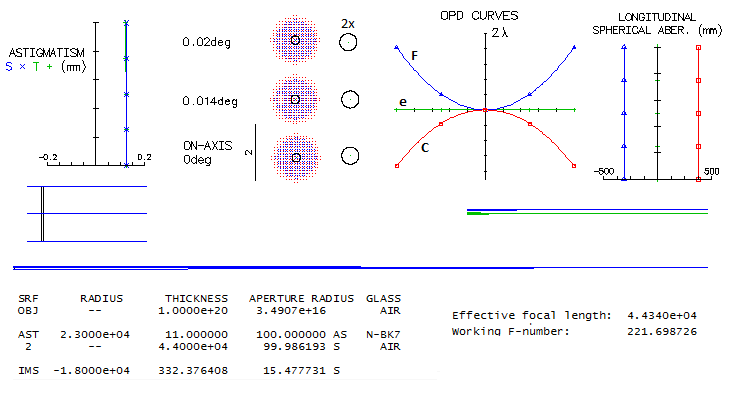
HEVELIUS' 45m TELESCOPE
Polish astronomer Johannes, or Jan Hevelius, the author of "Selenographia"
(1647, Gdansk, Poland) and the man who named the famous variable star in
the constellation of Cetus "Wonderful" ("Mira"), spent many nights
observing without a telescope, making measurements with brass sextants
while mapping the night sky. But he also built one of the most
spectacular telescopes ever, a 45-meter long refractor, which he
described and depicted in his "Machina coelestis" (1673). Its
objective was a single plano-convex lens - customary in those times - of
eight inch, or, 0.2m in diameter (~f/225). Long enough to eliminate
chromatic aberration? Here's what raytrace says:
The F and C lines average out at ~1.6 waves P-V, comparable to about 3
waves P-V with secondary spectrum. That is the level of a 100mm f/4
achromat. All other aberrations are entirely negligible. Same goes for
eyepiece aberrations, even a plano-convex singlet. A relatively high
200x magnification would require a 222mm eyepiece f.l. which would need
a 4-degree apparent field radius to cover the 0.02-degree (15.5mm)
objective image radius.
Others were using similar objective lenses, like Huygens in the Dutch Republic
(for his "aerial telescopes"), and it is known that Newton had a lens of
8 inch aperture and 170 feet (nearly 52m) focal length, which he gave to
the Royal Society in 1724. No doubt, the enormous light gathering power
of these lenses for the time, with higher magnifications possible, was
the main reason the astronomers went through the pains of building huge
mounts to hold them, very awkward and limited in their motion range. At
the time, due to the low reflectivity of speculum mirrors - a two mirror
system, with obscuration, would transmit only about 1/3 of the incoming light - a
comparable in light gathering power reflector would need to have over
0.5m in diameter.
Built in the late 1780s, Herschel's reflector was much shorter than
Hevelius' refractor. But it used a 1-ton 48-inch (1.2m) diameter metal
mirror, with reflectivity of about 66% (less in the blue, more in the
red). While it also required massive mount, with observing platform on
the side, it had much better stability and range of motion. To avoid
further loss of light at the diagonal mirror, both due to transmission
loses and obscuration, Herschel decided to tilt the mirror and observe
its image at the side of the telescope's front end. That, of course,
means that the image was significantly degraded by astigmatism and coma.
How much?
In order to bring the final focus out of the incoming light, Herschel
needed to have the axial ray reflected at 4°, i.e. to tilt the
mirror by half as much, or 2°. That took the final focus nearly 9.5 inch
out of the axial incoming pencil, but what tilt caused at the focus was
horrendous, in the form of 36 waves P-V of astigmatism and coma in the
field center. The asymmetric ray spot plot - and the diffraction image -
are about 1mm large, which amounts to 17 arc seconds angular size.
Extending field radius toward incoming light shows diminishing error,
but we need to go - expectedly - as much as 2° (over 0.4m) off to reach
the point where coma and astigmatism disappear. Of course, that is the
focal point of the 2° incoming pencil in the plane containing optical
axis and field center. Rotating this field around mirror axis by 360° we
can visualize the field at any point on the side of the mirror. Graph to
the right of the ray spot plots shows how astigmatism explodes toward
the farther half of the field (the astigmatic plot is for 1-degree
tilted image field), hence we can concentrate on the half
closer to the incoming light. The actual field that can be actually
observed is only a small fraction of this expanded field: for a singlet eyepiece of 86mm focal length (140x), it corresponds to less than
10° apparent field radius, or 15mm (1/14 of a degree true field radius).
By tilting the eyepiece (double-convex singlet, as used by Herschel) astigmatism can be
nearly cancelled out, but coma remains, in excess of 14 waves P-V. Also,
lateral color quickly emerges away from field center, although it
doesn't really matter considering the magnitude of coma. It is not
possible to correct both, astigmatism and coma with this small singlet
lens. While the coma blur is nearly as large as the original one - it is
due to the corresponding blur size for given level of aberration being
2.5 times larger for coma - its effect is significantly smaller. Still,
taking that some 80% of the energy is contained within the sagittal 1/3
of the coma blur, it comes to about 0.3mm, or 5 arc seconds in diameter
- the level of a 22mm aperture.
What did Herschel do faced with the practically useless telescope at its
intended focus? He could always stop down the aperture. In fact, at low
magnifications - relatively speaking - it was unavoidably happening due
to the eye pupil being smaller than the ep exit pupil. For the same 86mm eyepiece, the exit pupil was 8.6mm. If Herschel's night-time
eye pupil was 6mm, it would effectively stop aperture by a 0.7 factor,
reducing the center field error to some 15 waves P-V of astigmatism+coma.
If he would then move 1° (little more than 8 inch) toward incoming
light, it would be further reduced to less than 4 waves P-V, with his
head only negligibly protruding into the incoming beam of the observed
image. The aberrated blur would have been roughly ten times smaller, or
some 1.7 arc seconds - not worse than the seeing blur most of the time
(of course, it would make the combined blur nearly twice larger).
But at the smaller exit pupils, if he couldn't come up with some sort of sophisticated
corrector, which we have no mention of, he could decide to stick his
head - and possibly shoulders too - into the incoming light (it is known
that early into using this telescope, Herschel would "hunt" good image
holding eyepiece in his hand).
As gross as it seems, even observing at
the point of best correction, with his entire head and a better part of
his torso in the incident pencil of light, would still cost him only a
half of the light he'd lose with a diagonal (even when observing at the
original field center, his entire head would have been in the incoming
2° pencil, but would have been out of the incoming light for the
observed field). And the diffraction effect due to the
obscuration surely is not prohibitive. As the simulations show, it would
somewhat deform and slightly tilt the central maxima, reshaping the first bright ring into
two significantly brighter side lobes. Encircled energy wise, it would
enlarge the 80% energy circle by 67% - comparable to the effect of D/3
linear central obstruction, D being the aperture diameter (of course,
for that he wouldn't even need to tilt the primary).
Really minor compared to the magnitude of tilt aberrations, as well as
other factors, like seeing, thermals and figure. We may never know how
did Herschel actually use this telescope but, at least for now, can't
exclude the possibility that, at high magnifications, his head was in the light he was looking
at.
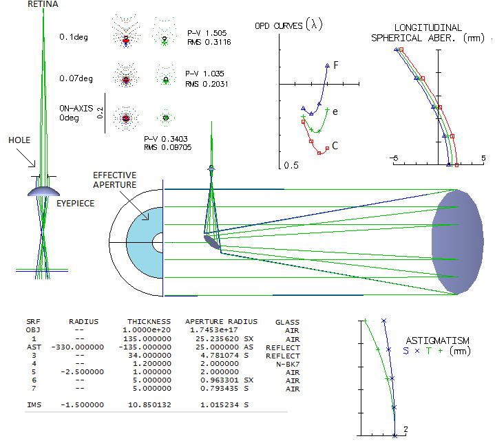
Mike I. Jones asked himself an interesting question: what kind of
improvement this Herschel's Big Eye would have with a simple Ed Jones
type corrector. Here's what he came up with:
Turned out, a pair of simple lenses would turn its intended focus
from being useless to a well corrected one. Taking 0.1° for the field
diameter (Herschel may have used bigger lenses than about 1 inch,
but even if he did they were probably stopped down to exclude the
poorly polished outer area; the smallest Herschel's eyepiece, as
investigated by W.H. Steavenson, was a biconvex lens 1/30 of an inch
in diameter, and roughly half as much - ~0.4mm - in focal length),
gives edge astigmatism of 0.082mm
longitudinaly, translating into 0.2 wave P-V (from 0.082/8F2).
Field center has nearly identical amount of aberration, but it is
mainly trefoil. However, dominant edge aberrations are coma and trefoil,
with astigmatism being practically negligible. Since astigmatism field
is nearly identical for the top and bottom field radius, only the
top half is shown. Best image tilt is not
quite the same for the top and bottom field diameter, because of the
presence of mild field curvature, but the effect is negligible.
Image tilt is little over 3°, which translates into over 0.5mm defocus
at field edge. Tilting the eyepiece generally doesn't work, but with
the eyepiece focal lengths that apply here this defocus is easily
within accommodation requirement of the eye (one diopter of accommodation
- i.e. the one needed when switching from infinity to 1m object distance -
is closely approximated by f2/1000, giving 10mm for a
100mm f.l. eyepiece). Accommodation-wise, the schortest f.l. eyepiece
here would be around 10mm, requiring 5 diopters of accommodation at
about x1200 magnification (this neglects eyepiece astigmatism and
field curvature, but
considering restricted field and fairly slow focal ratio, it
is not a significant factor - such eyepiece would have only 1/10
as "large" a field, or so, hence no accommodation to speak of).
For Herschel and his Big Eye, this two-lens corrector, technologically
quite within the reach at the time, would have been a gift from Heaven.
THE PLUTO TELESCOPE
Everything is relative, so a telescope from the late 1920s - which
is actually astrograph - is an early bird when it comes to what has
become the mainstay of professional astronomy: astrophotography or,
nowadays, astronomical imaging. In its basic form, it is a 300mm f/5 Cook
triplet, consisting of a three widely separated singlets (BAK1/F2/BAK1). Optical
prescription is given in a book "Telescopes, eyepieces, astrographs" by Smith/Ceragioli/Berry
(p407). Looking at its ray trace spot plots below, one would think
it is pretty much useless - at least by today's standards - but it is
the instrument used in the 1930. discovery of Pluto by Clyde Tombaugh
(Lowell Observatory, Flagstaff, Arizona).
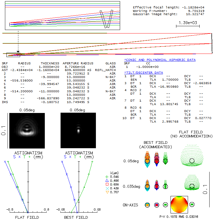
The triplet produces nearly flat field, whose curvature becomes not
negligible only due to the very wide 7.5-degree field radius (178mm).
The optimal image curvature, according to OSLO, is somewhat more relaxed
than the one given in the book (20m vs. 15m radius), and it does not
find the 2.2 wave P-V center-field defocus toward the curved edges given
in the book beneficial - to the contrary. Otherwise, the OSLO output is
very similar to that given in the book, and adds the colored output
for five different wavelengths, as well as diffraction-based information
on point-image energy distribution. The field here is limited to 6° radius since
due to vignetting at the front lens illumination already falls down to about 80%
(the actual instrument was used with 7.5° field radius).
It is the price to pay for placing aperture stop just behind the
middle lens, which reduces magnitude
of off axis aberrations.
The ray spot plots tell immediately that chromatism significantly
exceeds in magnitude monochromatic aberration across the entire image field (the
little black dot is the 0.43μm wavelength Airy disc). The
chromatic shift graph covers the 0.37-0.49 micron range with
the photo emulsion sensitivity, normalized to 1 at 0.43μm wavelength,
falling to about 0.2 at either end. Note that the graph shows defocus with
respect to wavelength's paraxial foci, and differs from the respective
total error at each wavelength, which can be either larger or smaller
at the location of best focus,
depending on the sign and magnitude of spherical aberration (longitudinal aberration
graph indicates the total error larger at the shorter, and smaller
at the longer wavelengths). The actual errors on axis are shown on the OPD
(wavefront optical path difference) graph, where it reaches about
7 waves P-V (averaged) already at 0.4μm and 0.46μ wavelength).
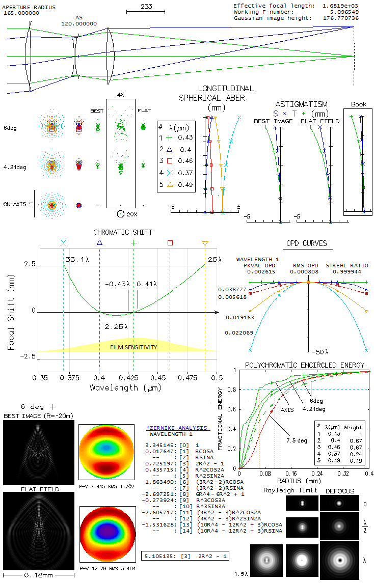
This excessive longitudinal chromatism makes mandatory filtering out
all wavelengths outside this range, and probably some inside it as well
(diffraction simulations bottom righ show the effect of defocus on
double star resolution). Lateral color is negligible vs. blur size.
In the optimized 0.43 μm wavelength, there is no aberrations to
speak of on axis; at 6° off, diffraction image (bottom left)
is somewhat elongated, approximately 0.07x0.15mm, with much smaller
brightest central area. With 1680mm focal length, this corresponds
to 8.5x18.4 arc seconds. Looking at the 80% encircled energy radius,
it is 0.126mm, 0.11mm and 6.2mm (14.5, 13.5 and 7.6 arc seconds) for
6°, 4.2° and 0° field radius, respectively (for the
five wavelengths, with given sensitivity; somewhat rough number, but
can be used as an indicator of the actual energy spread). The dashed
plot represents the defocused, somewhat more strongly curved field as given
with the original prescription; shown is for 6° field radius,
with the similar difference vs. best field in OSLO at 4.2°. Evidently,
for better resolution a further spectral range narrowing is needed,
but it would mainly be effective toward field center.
Best field
does not fall into the astigmatic field shown, because the graph
shows only primary and the conventional secondary astigmatism,
and not the effect
of odd higher order aberrations present, which change the best
image location. Zernike terms for the optimized wavelength at 6°
(best image field) indicate
that the dominant terms are primary spherical aberration (#8) and secondary
astigmatism (#11), followed by primary (#6) and secondary coma (#13). However, since
any spherical aberration is practically non-exsistent on axis, the
primary spherical term can only be lateral spherical aberration (one
of the secondary Schwarzschild aberrations), which has identical form
but increasing with the square of field height. Similarly, the primary coma and
astigmatism (to some extent) terms are actually lateral coma, of the
same form like primary coma but increasing with the cube of field radius,
and lateral astigmatism, of the same form as primary astigmatism but
increasing with the 4th power of the field height. Zernike terms are
nearly identical for the flat field, except that the dominant term
becomes defocus (#3, boxed). To illustrate the extent of higher-order
aberrations here, just omitting the tertiary spherical aspheric
(i.e. 8th order) term on the 4th surface
would result in over two waves P-V of tertiary spherical on axis.
Below is shown the difference between the defocused mode, described
in the book as the actual operating mode, and the one above, better according
to OSLO. Best image surface in OSLO is initially determined based on the
P-V/RMS wavefront values. They are not always reliable indicator with
large errors, but this time they did correspond to image surface with
nearly smallest spots, as well as the smallest encircled energy radii (for
80% EE). The output is limited to the three wavelenghts used in the book,
with added diffraction simulations corresponding to the ray spot
plots (normalized to 0.005 of the central diffraction intensity).
Both, ray spot plots and 80% encircled energy radius favor the focused
image. The choice for defocused image was probably made based on the
dense portion of ray spot plots becoming more even in size across the
field, with a logical assumption that defocusing toward the curved edges
will also decrease the error in the outer field. Neither one is correct,
according to OSLO. The very low normalization value, needed to show at least
a hint of the wide halo of energy spread around central diffraction
maxima (mostly due to chromatism closer to axis, and due to both chromatism
and off axis aberrations farther off) makes diffraction images somewhat
deceiving, suggesting that most of the energy is in the bright central part.
For instance, at 3° off axis with the defocused image, the central
bright spot fits in about 1/6 of the 80% energy circle, and contains
only about 25% of the energy (which is well over a magnitude loss,
or effectively correponding to the twice slower photographic speed).
At the 5-degree radius, images are noticeably
larger, and at 7° they are roughly half arc minute in diameter.
It is interesting that simply by using SF2 instead of F2 for the middle
element - with weaker aspherics, and somewhat stronger front radius to
bring F and C best foci together - this objective becomes nearly as
optimized for the yellow-green
centered spectrum.
TAYLOR (COOKE) TRIPLET
At the end of the 19th century, Dennis H. Taylor, who worked as a
chief engeener for T. Cooke and Sons of York, England, invented a
photographic objective capable of producing very wide, flat, well
corrected image (U.S. Patent #568,052, September 1896). In its
simplest form, it consists of a negative
lens sandwiched between two positive singlets, ordinary flint and
crown (same glass for both positive singlets), somewhat separated
one from another. While similar correction can be obtained with
a pair of lenses, the reason Taylor split the positive component
is that a triplet has significantly lower distortion,
and can maintain flat field with very close objects (e.g. for
copying and enlarging). Taylor claims in the patent application that
the new quality of his triplet vs. prior forms (Petzval orthoscopic
lens, Sutton, Dallmeyer, Ross triplets) is that it uses more efficient
correction mode, based on the compensating effect of the negative
element vs. positive ones, unlike "diaphragm correction"-based
predecesors (for that reason,
in his triplet,
power of the negative element nearly equals that of the two positive
elements combined, while in the prior forms it is only a fraction of
the positive power). Even if the Taylor triplet is a photographic objective,
it is interesting as one of the most famous objectives historically,
and to illustrate the difference in correction level vs.
astronomical objective.
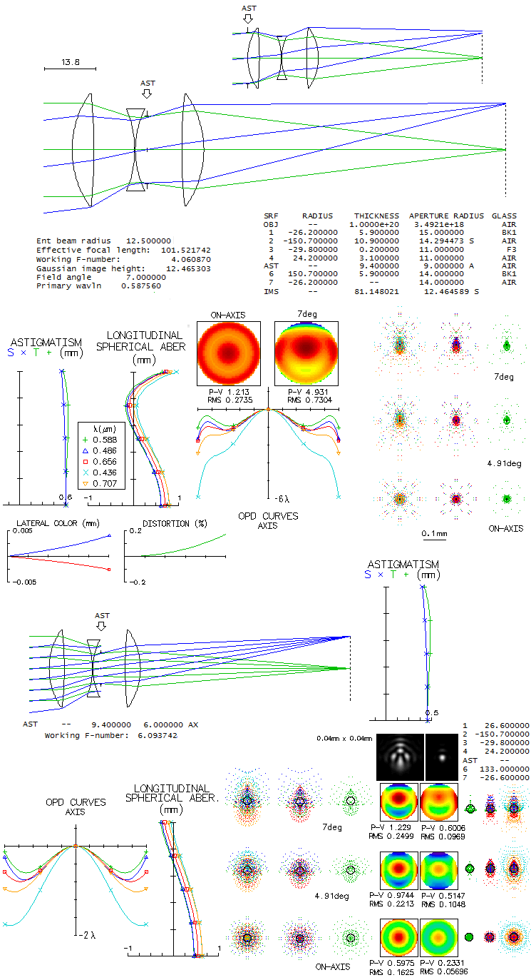
Below is a raytrace of the Taylor "Series I" triplet, as specified in his
patent application. According to the patent, at f/4 it produces a well-defined
image over photographic plate whose greater side equals one half
of its focal length. Taylor specifies the glasses by their D-line
refractive index and G-C line dispersion. While there is no
exact match with contemporary glasses, there are nearly identical
glasses that produce a very similar result. Important property
of this objective is that the stop is not at the front lens, but
behind the middle, negative element. It is where the relative
aperture is controlled, but more important is that it nearly
eliminates coma (with the stop at the front surface, the error at 7°
off at f/4 would have been over 20 waves P-V, mainly due to coma).
Diaphragm radius for an f/4 is around 9mm (8.85mm in the patent).
In order to minimize spherical aberration at f/4 the 1st and last
radius were made slightly stronger (originally 26.4mm, with the
corresponding axial P-V error of 2 waves). Note that
spherical aberration can be minimized only for one given f-ratio;
with the original prescription, it would take 21mm opening, i.e.
a bit faster than f/5, when the axial P-V error drops to 0.4 wave.
The color error is tightly related to the central line error, with a
partial exception of the violet g-line, having somewhat more of defocus
error. The field radius is taken to be 7°, which is when vignetting
at the front lens, due to its physical dimensions, starts.
Most of the P-V wavefront error at 7° off comes from the
top wrinkle on the wavefront, due to higher-order coma, but the
ray spot plots preserve a compact core, nearly unchanged in size
across the field.
The patent application also specifies several others configurations,
most of them with the split middle element, the main purpose of splitting being
better correction of spherical aberration. They claim larger corrected
fields, but are also generally of smaller relative aperture (up to f/8).
Since the primary arrangement, shown above, also have good correction
of spherical aberration in such relative aperture range, the advantage
of more complex arrangement may be limited to some special cases.
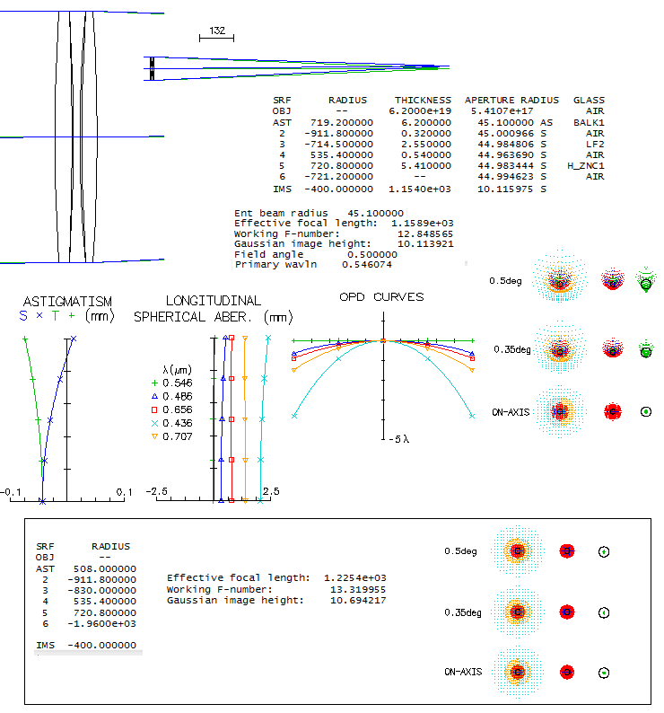
DOLLOND TRIPLET
Toward the end of his life, John Dollond started experimenting with
triplet objectives, wanting to minimize spherical aberration of the
doublet, increasing exponentially with the aperture. His son Peter
took over after his father's death and, coming into possesion of
suitable glasses, produced a number of large (for that time) 95mm
triplet refractors during the 1760-ties. In 1771 he sold a 90.2mm
triplet refractor to Reverend Francis Wollaston, who bequeathed it
to the Astronomical Sociaty of London. This instrument was
registered by the Royal Astronomical Society, and its optical
prescription is known (A Dollond-Wollaston telescope, Dall, Hysom
and Ronan). The original glasses - light flint sendwiched between
two near-identical crowns - are long time out of use, but close
replacements can be found among todays obsolete glases (Hoya's ZnC1
is a slightly better fit than Schott ZK1 zinc-crown). Below is
raytrace of this reconstructed triplet.
Spherical aberration correction is impecable, while chromatic correction
is at the level of a 100mm f/15 doublet achromat. Coma is present but
visually inconsequential, at the level of f/8.2 paraboloid (6.1mm
diffraction-limited field radius). Lenses are very thin by today's
standard, probably the consequence of dificulties in manufacturing
homogeneous glass. Coma can be easily corrected by re-balancing
R1 and R6 power (bottom, boxed).
It is believed that John Dollond turned to the triplet objective
in an attempt to better control spherical aberration. He probably
knew it drops exponentially with the increase in lens focal length,
so splitting a positive lens in two separate lenses would would
significantly reduce their aberration contribution. Indeed, if we
scale his 32mm f/24 objective to a
100mm f/12, it suffers from prohibitively high spherical aberration
(2.2 waves P-V). It could be corrected by changing one of the inner
radii and, to maintain needed negative-to-positive power balance
needed for correction of longitudinal chromatism, accordingly change
one of the outer radii. What cannot be corrected with given lens
shapes is coma, which is at the level of an f/5.3 paraboloid (linear
field, for changed R3 and R1). It implies that Dollond went with a triplet configuration
for relatively fast systems not only because he didn't know that
he can control it by balancing
two inner radii in a doublet, but possibly also in order to avoid
significant coma. That was his alternative to a long-focus objective.
At a small relative aperture, such is, for instance,
10-foot Dollond refractor of the Stockholm Observatory (100mm f/30),
the same scaled objective has spherical aberration at the
acceptable 0.15 wave P-V level (it could
be easily made negligible by a change in one of the inner radii). Coma
is negligible, at the level of an f/11 paraboloid.
◄
13.9. Eye spectral response
▐
14.2. ATM telescopes
► |
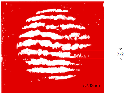 In addition to significant chromatism, lenses used at the time were
likely to have significant fabrication errors, i.e. figure errors
and roughness. This particular
lens - among some others that Galileo used - was tested interferometrically
(Optical tests of Galileo lenses,
Greco, Molesini and Quercioli, 1992), and as the image at right shows,
the test indicates it was below diffraction limited in that respect
(perfect wavefront would produce straight, evenly spaced lines, with smooth,
staright edges). Bright low-contrast resolution limit of this lens
was about 14 arc seconds due
to chromatism alone, and probably around 20 arc seconds (1/2 the average
Jupiter diameter) with the fabrication
errors included.
In addition to significant chromatism, lenses used at the time were
likely to have significant fabrication errors, i.e. figure errors
and roughness. This particular
lens - among some others that Galileo used - was tested interferometrically
(Optical tests of Galileo lenses,
Greco, Molesini and Quercioli, 1992), and as the image at right shows,
the test indicates it was below diffraction limited in that respect
(perfect wavefront would produce straight, evenly spaced lines, with smooth,
staright edges). Bright low-contrast resolution limit of this lens
was about 14 arc seconds due
to chromatism alone, and probably around 20 arc seconds (1/2 the average
Jupiter diameter) with the fabrication
errors included.


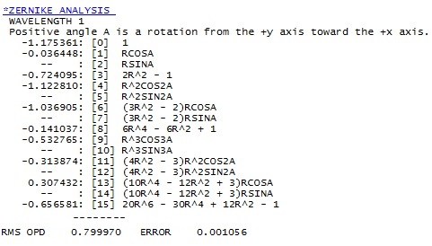 At 7° off the main components of the Zernike
reconstructed wavefront are primary astigmatism (4) and primary
coma (6), followed by defocus (3), secondary spherical (15), and
trefoil (9). Secondary astigmatism (11) and coma (13) are near negligible,
and terms beyond 15th are entirely negligible.
As mentioned, spherical aberration can be
minimized only for a single f-ratio value. Reducing the stop size
to 6mm, i.e. decreasing relative aperture to f/6.1, also reduces
spherical aberration, but leaves it unbalanced, due to the
secondary spherical aberration being reduced more - nearly entirely -
than the primary s.a. (bottom). It can be corrected by tweaking the
front and rear radius, with the coma induced by it minimized by
making R6 stronger. The result is a system with low spherical
aberration and nearly perfect image over 14° field (bottom
rightmost; it is
only a simple optimization - more thorough one could produce better
result).
At 7° off the main components of the Zernike
reconstructed wavefront are primary astigmatism (4) and primary
coma (6), followed by defocus (3), secondary spherical (15), and
trefoil (9). Secondary astigmatism (11) and coma (13) are near negligible,
and terms beyond 15th are entirely negligible.
As mentioned, spherical aberration can be
minimized only for a single f-ratio value. Reducing the stop size
to 6mm, i.e. decreasing relative aperture to f/6.1, also reduces
spherical aberration, but leaves it unbalanced, due to the
secondary spherical aberration being reduced more - nearly entirely -
than the primary s.a. (bottom). It can be corrected by tweaking the
front and rear radius, with the coma induced by it minimized by
making R6 stronger. The result is a system with low spherical
aberration and nearly perfect image over 14° field (bottom
rightmost; it is
only a simple optimization - more thorough one could produce better
result).